When I originally suggested what Tunborough recognised as similar to an orifice plate I was just thinking of a 0.5mm (ish) thick disc with a hole in it wedged in the pipe where the calibrator goes. That a fancy orifice plate is a real thing used for measurement suggests that the flow dynamics are simple. And another one with a slightly bigger hole.
So the effort would not a great deal more than doing another two sets of measurements.
Blowing machine
-
Terry McGee

- Posts: 3339
- Joined: Sun Dec 12, 2004 4:12 pm
- Please enter the next number in sequence: 1
- Location: Malua Bay, on the NSW Nature Coast
- Contact:
Re: Blowing machine
Yes, I'd been thinking along the same lines when I suggested orifices as an option to calibrators. But then I got a bit nervous when Tunborough started talking about long straight tubes with pressure takeoffs before and after the plate! But again, not ruling anything out if practical to make and essential to further progress.
-
Tunborough
- Posts: 1423
- Joined: Sun Dec 05, 2010 2:59 pm
- antispam: No
- Please enter the next number in sequence: 10
- Location: Southwestern Ontario
Re: Blowing machine
We definitely want a longer tube. The Generation is an outlier, and I'd want to rule out any irregularities that might explain that. I don't think we need a standardized gap, but I would be more comfortable with a 30 or 40 mm minimum.Terry McGee wrote: ↑Fri Feb 24, 2023 4:49 pm From that I have a short length of nominally 1/2 irrigation tube to join it to the whistle. Hmmm, perhaps too short a piece. It currently overhangs 18.35mm from the end of the T-joiner, and that means the fairly pointy Generation beak runs right up to the joiner. That might introduce some error as the rectangular slot of the windway entry is a poor match for the circular bore of the joiner. I should probably cut a longer piece of tube so that no whistle beak can get too close to the joiner. I'll do that and check to see if it makes any noticeable difference at the high end. What do we think, allow say a 20mm minimum gap from windway entry to T-joiner outlet? That will mean bigger gaps for blunter beaks, and for calibrators. Or do we need to get really picky and standardise the gaps?
Re: Blowing machine
Thanks very much, Terry.
Plotted up the tone data. Interesting positioning.
Been a long, tiring day here. That is all.
-
Terry McGee
- Posts: 3339
- Joined: Sun Dec 12, 2004 4:12 pm
- Please enter the next number in sequence: 1
- Location: Malua Bay, on the NSW Nature Coast
- Contact:
Re: Blowing machine
OK. I'd be getting worried that we're leaving the pressure takeoff point a fair way behind. (It's currently fed by the T-Junction.)Tunborough wrote: ↑Fri Feb 24, 2023 9:14 pmWe definitely want a longer tube. The Generation is an outlier, and I'd want to rule out any irregularities that might explain that. I don't think we need a standardized gap, but I would be more comfortable with a 30 or 40 mm minimum.Terry McGee wrote: ↑Fri Feb 24, 2023 4:49 pm From that I have a short length of nominally 1/2 irrigation tube to join it to the whistle. Hmmm, perhaps too short a piece. It currently overhangs 18.35mm from the end of the T-joiner, and that means the fairly pointy Generation beak runs right up to the joiner. That might introduce some error as the rectangular slot of the windway entry is a poor match for the circular bore of the joiner. I should probably cut a longer piece of tube so that no whistle beak can get too close to the joiner. I'll do that and check to see if it makes any noticeable difference at the high end. What do we think, allow say a 20mm minimum gap from windway entry to T-joiner outlet? That will mean bigger gaps for blunter beaks, and for calibrators. Or do we need to get really picky and standardise the gaps?
Supposing we ditch the T-junction, swapping it for a coupler of the same bore, used solely to join the 1/4" flexible bore supply tube up to the 1/2" bore stiffish irrigation tubing that couples to the heads. We leave a suitable amount of length (say 40mm?) from the end of the coupler, then I make and attach a delrin collar to go outside the 1/2" bore irrigation tube. The collar to be say 30mm diameter and 20mm wide? I drill a lateral hole in that collar and through into the space inside the tube, and attach a spigot that will interface with the 4mm Digital Manometer tube. I glue those 3 items (tube, collar and spigot) in place so they can't come adrift or leak. Then we leave say another 20mm from the spigot point plus the 20mm needed to plug the beaks into? So now the pressure take-off point is about 20mm above the tip of the beak, and it's in 13mm tubing, not a 9.5mm T-Joiner. We could probably sneak it a bit closer to the beak if we wanted....
Waderyarekon? (Australian slang for "What is your considered expert opinion on the proposal submitted?")
Or better suggestions?
-
Tunborough
- Posts: 1423
- Joined: Sun Dec 05, 2010 2:59 pm
- antispam: No
- Please enter the next number in sequence: 10
- Location: Southwestern Ontario
Re: Blowing machine
If you're up for that construction, it would be a pretty indisputable arrangement. I can't think of any improvements to it.
-
Terry McGee
- Posts: 3339
- Joined: Sun Dec 12, 2004 4:12 pm
- Please enter the next number in sequence: 1
- Location: Malua Bay, on the NSW Nature Coast
- Contact:
Re: Blowing machine
OK, done. I haven't glued it yet in case we want to make a design change. But it was a tight fit, and a suck test could pull a vacuum so I don't think its a problem.
I left the old T joiner in place of the straight coupler I will use. That way I was able to compare the old (via the T joiner) and the new (via the spigot). I just covered the other hole when not in use. And I used the Digital Manometer and checked the results twice.
What does that say to us?
I left the old T joiner in place of the straight coupler I will use. That way I was able to compare the old (via the T joiner) and the new (via the spigot). I just covered the other hole when not in use. And I used the Digital Manometer and checked the results twice.
Code: Select all
Test new Pressure-Take-off arrangement
Flow	Old	Res
20	74	0.430
40	306	0.437

Flow	New	Res
20	75.6	0.435
40	310	0.440
Re: Blowing machine
Terry, is there any chance you could snap a picture + post it ? I'm simply better at images than words.Terry McGee wrote: ↑Sat Feb 25, 2023 5:03 pm. . .That way I was able to compare the old (via the T joiner) and the new (via the spigot). . .
-
Terry McGee
- Posts: 3339
- Joined: Sun Dec 12, 2004 4:12 pm
- Please enter the next number in sequence: 1
- Location: Malua Bay, on the NSW Nature Coast
- Contact:
Re: Blowing machine
OK, here we go.... 
Across the top, from L to R, we have
- the blue airline coming in from the workshop air supply, the lever switch to disable it, and the brass snap-on connector going to the pressure regulator
- note the low pressure registering on the regulator pressure meter
- the output of the pressure regulator hooks to the flow regulator ( big black knob to its right).
- output of the flow regulator goes over to extreme right of the panel, plugging directly into the first 20L/Min meter, and via the chrome valve with the red knob, to the second 20L/Min flow meter.
- the red knob is in closed position so only the first 20L/Min meter is in service
- the outputs of the pair of flow meters are combined and fed to one side of the T junction
- the side exit of that T junction is closed with a rubber bung
- the other end of the T-junction feeds our new whistle connector
- the manometer is connected to a spigot on that new whistle connector
- the new whistle connector has the Old Generation whistle plugged into it and taped over the join
- the several turns of blue tape at the top of the brass tube identifies and helps secure the chosen tuning length
- the top three holes are covered with tape to select the note G (sorry, out of focus!)
- my phone has the Instrument Tuner Pro app loaded and is showing the pitch at 0 cents
- the left hand flow meter is showing 10L/Min
- the manometer is registering 8.6 CM(H20)
- also visible are the black delrin calibrators I've made so far, the Feadog Mk1, and a newer Generation with its head off.
- and a couple of scalpels with blades #11 and #10, 6" steel rule and calipers off to right.
- and on the bench beside the manometer, a blue water stain, in memory of the U-tube Manometer.
- once we confirm we're happy with the new whistle connector, that T-junction will be replaced by an inline coupler
Hope that helps!
-
Tunborough
- Posts: 1423
- Joined: Sun Dec 05, 2010 2:59 pm
- antispam: No
- Please enter the next number in sequence: 10
- Location: Southwestern Ontario
Re: Blowing machine
Bernoulli was right.
Bernoulli's principle says v^2/2 + P/rho is a constant at a given flow. Given that the diameter at the tee junction is 9.5 mm and the diameter at the spigot is 12.5 mm, the constant works out to:
- at 20 L/min, 620 at the tee and 626 at the spigot
- at 40 L/min, 2564 at the tee and 2568 at the spigot
This is well within our margin of error.
-
Tunborough
- Posts: 1423
- Joined: Sun Dec 05, 2010 2:59 pm
- antispam: No
- Please enter the next number in sequence: 10
- Location: Southwestern Ontario
Re: Blowing machine
Absolutely awesome.

-
Terry McGee
- Posts: 3339
- Joined: Sun Dec 12, 2004 4:12 pm
- Please enter the next number in sequence: 1
- Location: Malua Bay, on the NSW Nature Coast
- Contact:
Re: Blowing machine
So, taking that as a sign we're heading in the right direction, I've swapped the T junction for a straight coupler, glued up the new Whistle Connector parts, and cut down the flow and manometer tube lengths to minimise bench clutter. It's all looking and feeling pretty secure now. And to test it at any time, I can use one of the calibrators. Indeed, I'll make a note down there of the readings to expect from a specific calibrator, and make a habit of testing the rig before connecting a new whistle.
Making sure that the connection to the whistle beak is airtight remains the biggest challenge. The fairly stiff plastic will squish to accommodate the general beak shape, but will then try to go round again, ejecting the whistle a bit and creating leaks. So I don't see much choice other than to tape it on as I did in the image above. A leak there of course will be fatal, but probably also show up during testing with really silly results.
Are we there yet, or do we need to make any more self-test devices?
-
Terry McGee
- Posts: 3339
- Joined: Sun Dec 12, 2004 4:12 pm
- Please enter the next number in sequence: 1
- Location: Malua Bay, on the NSW Nature Coast
- Contact:
Re: Blowing machine
I should probably explain what the other items not part of this setup are. Inside the box lurks an aquarium type pump, whose output comes out at the bottom left hand of the unit, below the regulator. It feeds the controller with the black and silver knob. That flow is directed through the Dwyer 1SCFH Air Flow Meter, and the pressure generated across the flow meter (and set by its needle valve) is connected to the Magnahelic Pressure Gauge. The output of the airflow meter is also taken via flexible tubing to a rubber bung with a hole it in. The whole thing is a Magnahelic Flute Leakage Meter, now marketed as:
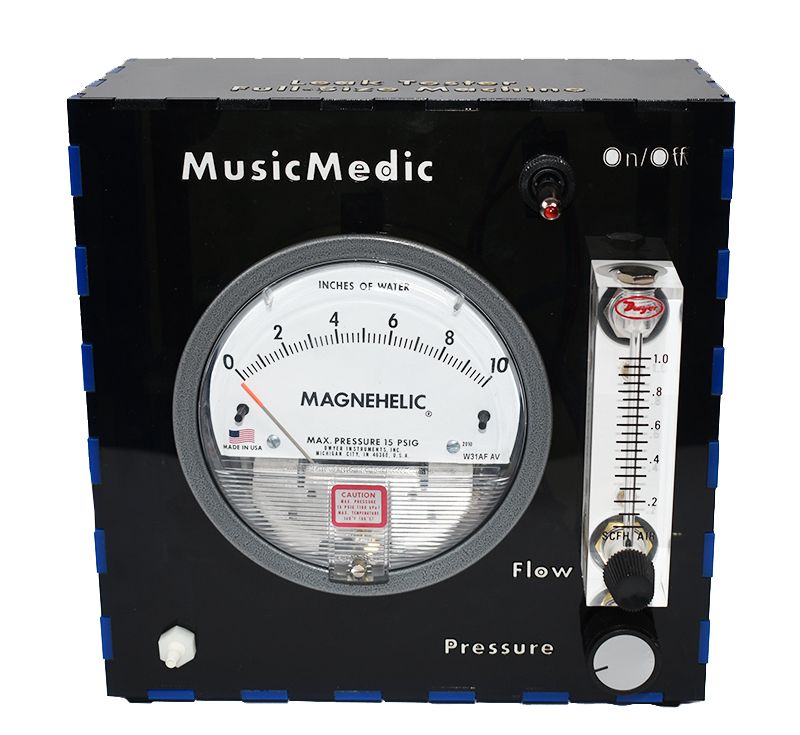
You plug the rubber bung into the end of a section of flute, cover all the other holes and you should see zero or very close to it on the Magnahelic gauge. It works down to very, very low leakages, for example it can easily read the leakage through the whorls of my finger prints. Indeed to stop that, I have to press very hard on the holes, or lick my fingers first! Because covering holes is a source of error, I have a big collection of rubber bungs to be able to plug any hole I'm likely to come up against.
Note that Dwyer prints on their meters what gas its calibrated for.
Amusing to compare the scales of flow in our two systems. A flute passes the leakage test if the Magnahelic reads 0.1 or less, which happens when the SCFH meter reads 0.1 which is equivalent to 0.047 L/Min. And we're driving our poor whistles at up to 40L/Min, 850 times harder!
And you can also see the 0-5mm H20 flow meter with its two connections unused.
Re: Blowing machine
O M G !!!
Mr. McGee, that is a *fine* bench !
Bring all of your whistles to Terry McGee !
He'll hook 'em right to see how they breathe
he'll measure the pressure, the flow, and the sound
you'll get so much data, your head will spin 'round !
Plus, nice little gizmo - MusicMedic. How are you marketing ?
Plus: thank goodness the Dwyer folks *label* the gas their flowmeter is for !
-
Terry McGee
- Posts: 3339
- Joined: Sun Dec 12, 2004 4:12 pm
- Please enter the next number in sequence: 1
- Location: Malua Bay, on the NSW Nature Coast
- Contact:
Re: Blowing machine
Yeah, I think we're starting to get somewhere now.
Ah, sorry, I didn't make that clear. Nothing to do with me except I bought one many years ago from the previous maker. These are now marketed by:Plus, nice little gizmo - MusicMedic. How are you marketing ?
https://www.musicmedic.com/catalog/prod ... tegory/68/
Yeah. I guess that's the benefit of buying them from a professional company like Dwyer, rather than a mass-market outlet like Shunhuan. Probably a good deal more expensive, but at least you know what you're getting!Plus: thank goodness the Dwyer folks *label* the gas their flowmeter is for !
Hmmm, I see they offer a 100mm tall scale version (double mine) with a 4-40L/Min range, calibrated for air. With or without brass valve.
https://www.dwyer-inst.com.au/Product/F ... F#ordering
No home should be without one....